27+ high level use case diagram
The Campbell diagram can be generated from machine design criteria or from machine operating data. Youll require to solder the wires so use the soldering flux and iron and place them out on the operation surface.
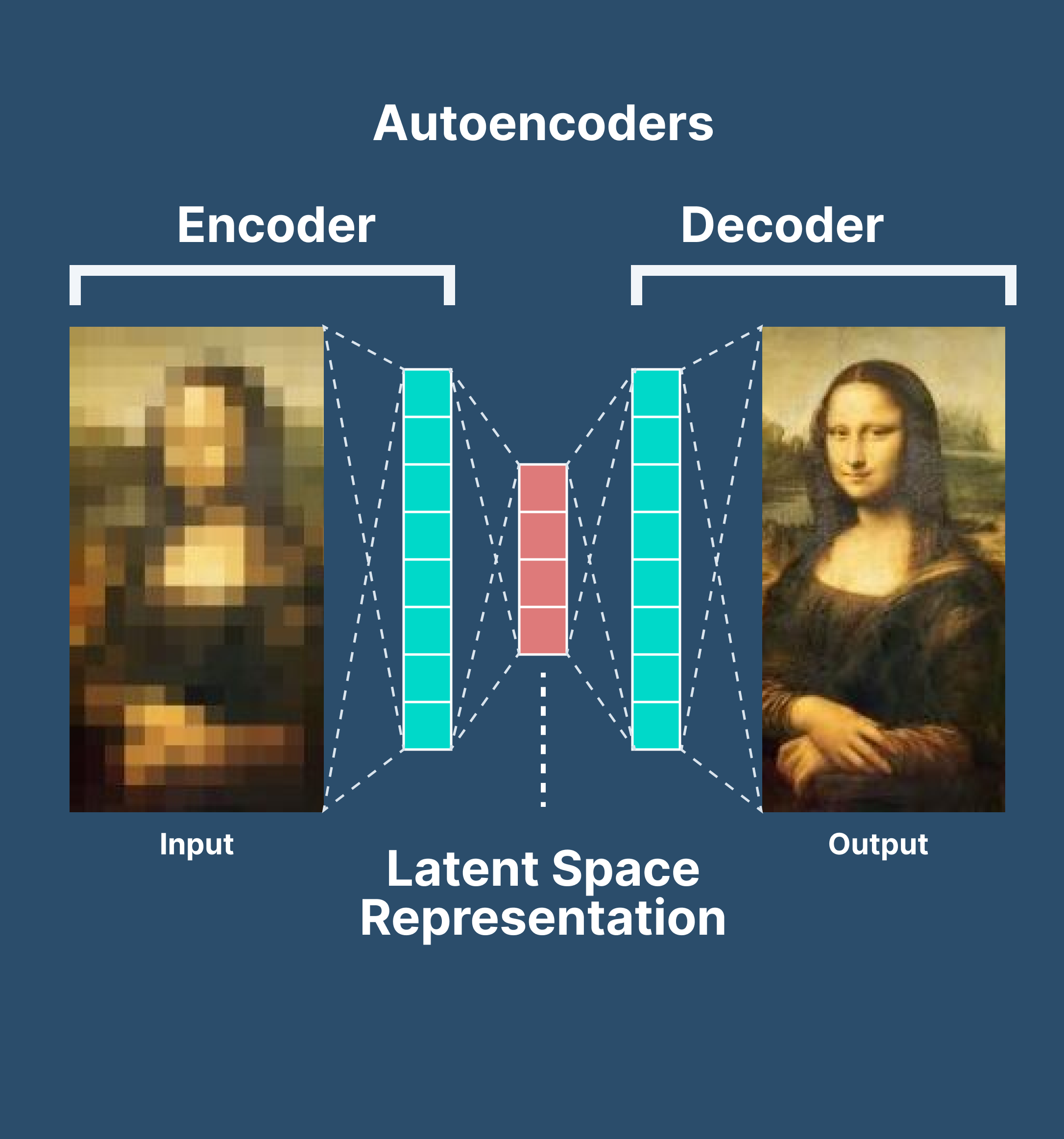
Autoencoders In Deep Learning Tutorial Use Cases 2022
The High-Level Design HLD gives the project stakeholders a birds eye view of the system at the end of the project.

. Its a basic overview of the whole Airline Booking System or process being analyzed or modeled. Because of the interest level a further explanation is presented here along with a sample and template for your use. Press on Actor in the diagram toolbar.
The Campbell diagram is an overall or birds-eye view of regional vibration excitation that can occur on an operating system. In 1987 Ivar Jacobson presented the first article on use cases at the OOPSLA87 conference. 16A24 Organization Decomposition Diagram 0200.
Load using unstable and low currents. 1910 Components of the High-Level III RM. The system frequency is along the Y axis.
The NP200 is a divorced style transfer case utilizing a jack shaft between a 2wd style transmission and the transfer case input yoke. At its core is the solution architecture the process through which a solution is generated to solve a. If youre wiring a particular form of electronic instruments that use specific wires soldered wires should be double-checked.
At least 10 below the base case 1 4 2 point. Actor in a use case diagram is any entity that performs a role in one given system. A SIPOC diagram is a tool used by a team to identify all relevant elements of a process improvement project before work begins.
Too hot and big. Np208 transfer case diagram. In this above circuit we have used the popular LM358 amplifier to amplify the signals from microphone.
This could be a person organization or an external system and usually drawn like skeleton shown below. It is similar to a block diagram. 16A23 Business Use case Diagram 0232.
To create a Use Case Diagram select Diagram New from the toolbar. This section has three steps in the case of the potentiometer connection. This is the next installment in a series of articles about the essential diagrams used within the Unified Modeling Language or UML.
System context diagrams show a system as a whole and its inputs and. He described how this technique was used at Ericsson to capture and specify requirements of a system using textual structural and visual modeling techniques to drive object oriented analysis and design. 20A27 Software Engineering Diagram 0034.
We should choose the circuit to be suitable for the load. Many recent inquiries and discussions have focused on the SIPOC diagram a tool used in the Six Sigma methodology. Keep Blank selected and click Next.
Posted By namita on June 27 2017. The NP200 is installed as a passengers side drop in the M715 M725 military Jeeps exclusively with the T98 four-speed transmission. Here we have used Low pass and high pass filters with Amplifier to reduce the noise in this sound level measurement circuit so that accuracy can be increased.
This is the Zero Level DFD of Airline Booking System where we have eloborated the high level process of Airline. The objects are further explained below. In the New Diagram window select Use Case Diagram and click Next.
The NP200 has a low-range of 1971 and is direct drive in high. Use case diagrams consist of 4 objects. All IT projects will require a High-Level Solution Design also known as HLD an artifact instrumental in the Analysis phase of the SDLC.
Enter System Use Cases as diagram name and click OK. In my previous article on sequence diagrams I shifted focus away from the UML 14 spec to OMGs Adopted 20 Draft Specification of UML UML 2In this article I will discuss Structure Diagrams which is a new diagram category that. It is so a large size and also too hot.
Also you can use a 6V relay to 12V by helping of a resistor. We need to use high watts of a resistor. A typical Campbell diagram plot is shown in Figure 5-25Engine rotational speed is along the X axis.
Use Case diagrams represent a set of Use Cases which are textual descriptions of how an actor achieves the goal of a use case. This Use Case Diagram is a graphic depiction of the interactions among the elements of. Drag it onto the diagram to create an actor and name it Customer.
16A25 Process Flow Diagram. 1909 Components of the III RM 0029. Use Case Diagram objects.
For Example Customer Places Order. 1908 Integrated Information Infrastructure Reference Model High level Model 0140. Reduction in embodied energy of building structure Select the percentage reduction in combined embodied energy of structure 20 and masonry walls.
Originally he had used the terms usage scenarios and usage. We will see that if used a too high current of the load. This diagram is a high level view of a system.
If you load use unstable currents.
How Ai Is Transforming The Insurance Industry 6 Use Cases

27 Easy To Edit Lesson Plan Examples Writing Tips

27 Cover Letter Formats Cover Letter For Resume Cover Letter Example Job Cover Letter

A Partial Energy Level Diagram Of The 4d 4f Ground State Term In Download Scientific Diagram

Meter Data Management System An Overview Sciencedirect Topics
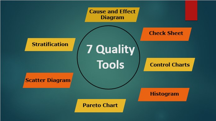
7 Quality Tools Learn Seven Best Types Of Quality Tools
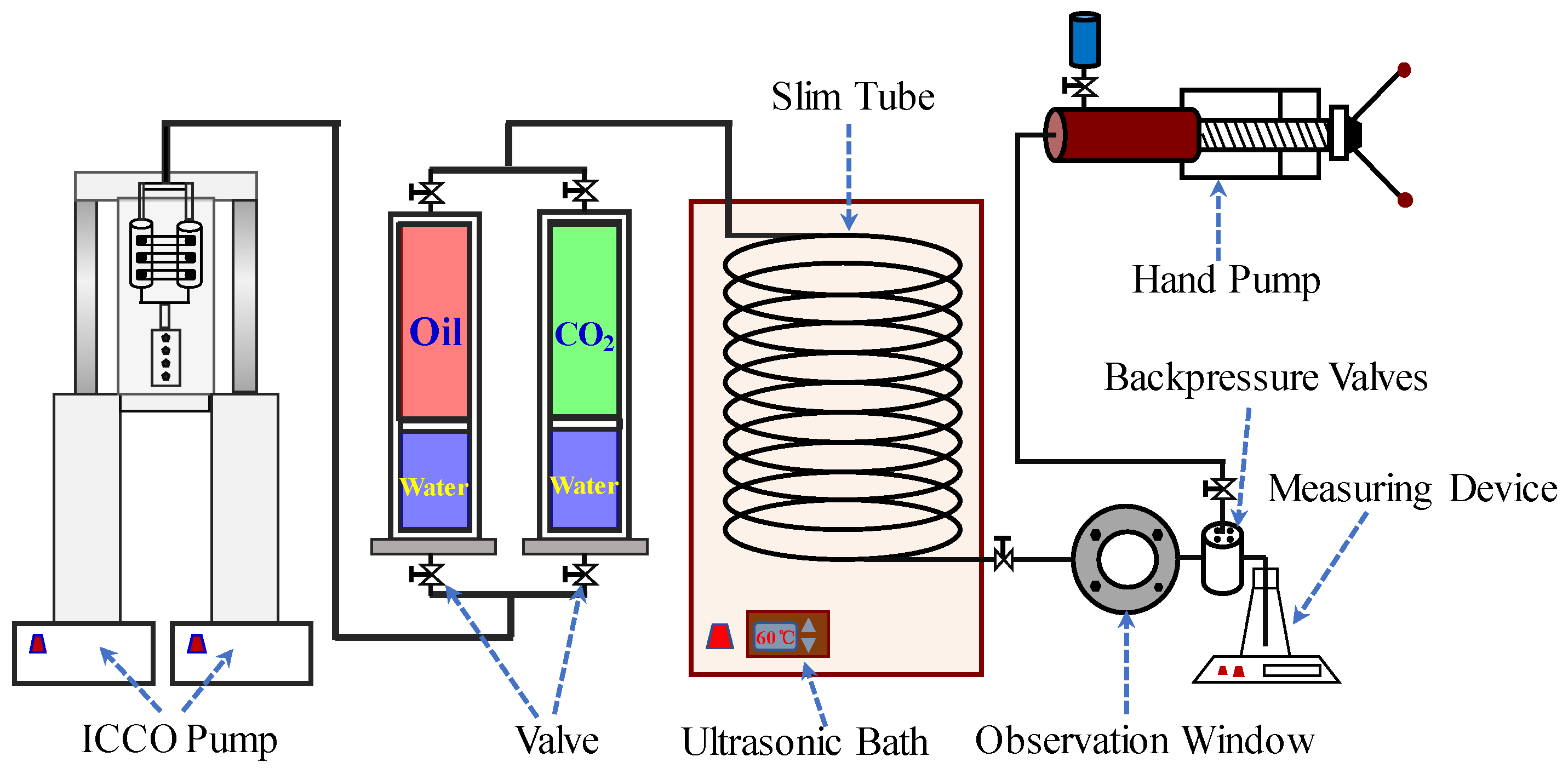
Sustainability Free Full Text How Is Ultrasonic Assisted Co2 Eor To Unlock Oils From Unconventional Reservoirs Html

Cd27 Expression Segregates Ifn G Versus Il 17 Producing Gd Cells In Download Scientific Diagram

How Ai Is Transforming The Insurance Industry 6 Use Cases

Report To Senior Management Template 4 Templates Example Templates Example Report Template Senior Management Word Template Design
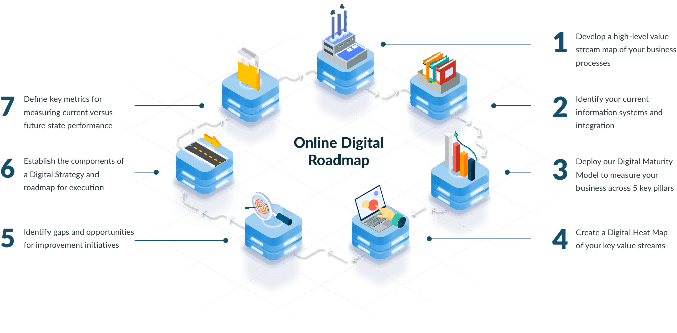
Lean Digital Leading Edge Group

2auev5bbgeynm

Autoencoders In Deep Learning Tutorial Use Cases 2022

9 Reinforcement Learning Real Life Applications

Real World Use Case With Cassandra Eddie Satterly Datanexus C S

Template Lab 37 Free Purchase Order Templates In Word Excel 66845114 Resumesample Resumefor Purchase Order Template Purchase Order Form Purchase Order

Energy Level Structure Of The 4d 4f Ground Configuration Level Download Scientific Diagram